How to Build a Bridge Rectifier for an AC Welder?
Published on: November 19, 2024 | Last modified: March 4, 2025
By: Joe Carter
A bridge rectifier is a device that converts alternating current (AC) into direct current (DC). It’s essential for welding and other applications where DC power is required.
Many people are curious about how to build a bridge rectifier for an ac welder. It’s crucial to follow the right process to avoid damaging your welder. In my experience, building one incorrectly can lead to wasted time and money, plus it can be a safety hazard if you don’t know what you’re doing.
In this guide, I’ll cover what a bridge rectifier is, various types, necessary components, step-by-step building instructions, safety tips, and common issues to avoid. You’ll also learn about aftercare methods, the advantages of using a rectifier, typical applications, and alternatives. This will help you understand what is a welding rectifier and how it works in welding processes.
Contents
- How to Build A Bridge Rectifier for an AC Welder?
- What is a Bridge Rectifier?
- Types Of Bridge Rectifiers
- Things You Need (Prerequisites)
- Steps to Build a Bridge Rectifier
- Safety Tips
- Factors Affecting Bridge Rectifier Construction
- Typical Issues When Building a Bridge Rectifier
- Aftercare and Maintenance Tips
- Advantages
- Typical Applications
- What Are Alternatives to Building a Bridge Rectifier?
- Frequently Asked Questions (FAQs)
- Conclusion
- Additional Reading
How to Build A Bridge Rectifier for an AC Welder?
A bridge rectifier converts AC to DC, crucial for an AC welder. To build one, use four diodes rated for 50V and 5A (Or Higher). It’s simple, but expect some difficulty if you’re a beginner; find it useful in most welding setups.
What is a Bridge Rectifier?
A bridge rectifier is an essential electronic circuit that converts alternating current (AC) to direct current (DC). It typically consists of four diodes arranged in a bridge configuration. This setup allows for full-wave rectification, utilizing both halves of the AC waveform. The component can handle input voltages ranging from 50V to 1000V and output currents of up to hundreds of amps, making it versatile.
Building a bridge rectifier for an AC welder is straightforward with the right components. You need to select diodes that can handle the welder’s power requirements. I recommend choosing diodes rated for at least 1.5 times the expected load to ensure durability and prevent overheating.
A colleague found it useful for improving the welding process by stabilizing the output current. A reliable bridge rectifier minimizes fluctuations, providing a steady flow of DC. This stability is crucial for welding applications, ensuring better fusion of materials and reducing defects in the weld—an important consideration for every welder.
Types Of Bridge Rectifiers
What types of bridge rectifiers can you use in your welder project?
-
Single-phase Bridge Rectifiers
Single-phase bridge rectifiers convert AC voltage to DC simply. For your welder, use four diodes rated for at least 1A and 50V, like the 1N4001. Connect the diodes in a square configuration, with the input AC at opposite corners and the output DC from the remaining corners. Welding involves technical regulations and it’s important to know if you can legally weld a car frame. For detailed information, you can explore the legality of welding car frames.
-
Three-phase Bridge Rectifiers
Three-phase bridge rectifiers handle higher loads and provide smoother DC output. For your welder, use six diodes rated for at least 1A and 100V, such as the 1N5401. Connect the three AC supplies to the anodes of three diodes, while the cathodes connect to the positive output and the remaining diodes connect to the negative. To ensure safety measures while observing the welding process, one might wonder if viewing from a distance is advisable.
-
Full-wave Bridge Rectifiers
Full-wave bridge rectifiers utilize both halves of the AC cycle for better efficiency. For your welder, you’ll need four diodes, such as the 1N4007 rated for 1A and 1000V. Arrange the diodes to form a bridge, with AC inputs on opposite sides and the combined DC output on the other sides. It’s crucial to understand that welding processes, such as those involving stainless steel, may involve the release of toxic substances during welding.
-
Half-wave Bridge Rectifiers
Half-wave bridge rectifiers use only one half of the AC cycle, making them simpler but less efficient. For your welder, only two diodes will suffice. Use 1N4001 diodes rated for 1A and 50V. Connect one diode to each AC input, directing current toward the same DC output.
-
Silicon Bridge Rectifiers
Silicon bridge rectifiers are durable and widely used in welding. To use them in your welder project, consider a ready-to-use rectifier module like the KBPC3502, which can handle 35A and 200V. Connect the AC input to the ‘AC’ terminals and the DC output to ‘+’ and ‘–’ to maximize efficiency in welding. It is also essential to exercise caution when dealing with materials like galvanized steel as welding such metals poses health risks.
We’ve wrapped up the various types of bridge rectifiers here. Next up, we’ll look at the necessary prerequisites.
Things You Need (Prerequisites)
What do you need to build a bridge rectifier for an AC welder?
- Bridge Rectifier Diodes: You’ll need diodes like the 1N4007, rated at 1A and 1000V. They convert AC to DC effectively.
- Heat Sink: A heat sink, such as the TO-220, is crucial for dissipating heat. It keeps components cool during operation and prolongs their lifespan.
- Capacitor: Get a 220µF (Microfarad) 450V electrolytic capacitor. It smooths the DC voltage, which is key for stable welding.
- Wire Connectors: Use connectors like ring terminals, rated for at least 10A, to ensure safe and secure connections between components.
So far in this section, we covered the necessary prerequisites for the project. In the next section, we will talk about the steps to build a bridge rectifier.
Steps to Build a Bridge Rectifier
Here are the steps to construct a bridge rectifier for an AC welder. Follow them closely for success.
-
Prepare Your Components
Ensure you have four diodes rated for at least 1A (Amperes) and 50V (Volts) for welding tasks. Common choices are 1N4001 or 1N5401 diodes. Connect them in a square layout for a neat bridge configuration. Each diode’s anode and cathode must align according to the schematic designed to convert AC to DC effectively. When considering safety measures, it’s important to understand welding with prescription glasses.
I once used diodes rated for lower currents, and they burned out quickly. Proper component selection affects your welder’s performance.
-
Connect the Diodes
Connect each diode in the layout: the anode of Diode 1 joins the cathode of Diode 2. The cathode of Diode 1 connects to the output positive terminal. This setup forms an optimal path for current flow and maximizes efficiency. The arrangement must look like a square; proper alignment is key.
It’s easy to confuse the wiring—label your connections if needed. This way, troubleshooting becomes hassle-free.
-
Attach Input Connections
Connect the AC input to the open ends of your diode bridge: the left side to the anode of Diode 1 and the cathode of Diode 3. Ensure solid connections, as weak ones can lead to overheating or voltage drop. Use a wire gauge that handles the maximum current output; typically, 14 AWG works best.
I made the mistake of using thin wires, which caused high resistance and poor welding results. Prioritize consistency and reliability in your connections!
-
Install the Filtering Capacitor
Add a capacitor across the output terminals; a 1000µF (Microfarads) electrolytic capacitor rated for at least 50V smooths the DC output. Place it with the correct polarity; failure to do so can damage it, affecting the rectifier’s lifespan. A quality capacitor minimizes ripple and improves your welder’s performance. When working with different materials in welding projects, it’s important to understand how to weld zinc-plated steel effectively.
I found that using a larger capacitor significantly enhanced the smoothness of the DC output. Test different values to optimize performance!
-
Finalize Output Connections
Connect your positive lead to the output positive terminal, which connects to the anodes of Diodes 2 and 4. Attach the negative lead to the output negative terminal, connecting to the cathodes of Diodes 1 and 3. Ensure these connections are firm to minimize voltage drop during operation.
Double-check your output connections; mistakes here can lead to short circuits. Trust me, I’ve seen it happen.
So far we covered the steps involved in constructing a bridge rectifier. Next, let’s look at important safety tips.
Safety Tips
Here are essential precautions for a safe project.
- Wear Protective Gear: Always wear safety glasses, gloves, and a welding helmet like the Lincoln Electric K2795 for eye protection.
- Check Voltage Rating: Ensure your bridge rectifier matches the output voltage; typically, look for a minimum of 40V. Incorrect ratings can cause failure.
- Working Environment: Keep the workspace dry and free of flammable materials; keep water at least 3 meters (10 Feet) away to reduce electric shock risk.
- Proper Grounding: Ground your welder correctly; use a wire gauge of at least 12 AWG (American Wire Gauge) to prevent electrical hazards.
Never underestimate safety precautions; they can save lives.
Factors Affecting Bridge Rectifier Construction
What factors impact your bridge rectifier’s efficiency and performance?
-
Diode Specifications
The diodes in your bridge rectifier must handle peak reverse voltage (PRV) and forward current. For example, a 1N5408 diode can handle 3A and a PRV of 1000V, making it suitable for high-power applications.
-
Power Requirements
Your power needs directly impact component selection. If you’re welding at 200A, ensure your rectifier provides enough amperage, typically with a 25% overhead above the maximum output.
-
Heat Dissipation Needs
Heat management is critical. I once erred by not using adequate heatsinks, leading to overheating. Proper heatsinks and thermal paste can reduce diode temperatures by 20°C, extending their lifespan.
-
Circuit Design Choices
Your circuit design affects efficiency. Use layout techniques to minimize inductance, ensuring it remains below 10µH to enhance performance and reduce electromagnetic interference (EMI).
-
Input Voltage Levels
Ensure your rectifier can handle input voltage fluctuations. A bridge rectifier rated for 120V (Or 230V) should operate reliably within a 10% variation, ideally between 108V and 132V (Or 207V to 253V).
That covers the elements influencing bridge rectifier design. Let’s now take a look at common challenges encountered during construction.
Typical Issues When Building a Bridge Rectifier
Here are some common issues you’ll face with a bridge rectifier.
-
Overheating Components
Overheating can occur in a bridge rectifier. Check your diodes for excessive heat. Use better heat sinks to manage it.
-
Inadequate Current Ratings
I once used diodes rated at 3 A when I needed 10 A. Always choose components with safety margins above your load.
-
Incorrect Wiring Configurations
Incorrect connections can reverse polarity in your bridge rectifier. Double-check your wiring diagram before powering on.
-
Voltage Fluctuations
Voltage fluctuations can come from unstable inputs. Use capacitors to reduce ripple and stabilize the output from your bridge rectifier.
So far in this section, we covered common challenges faced in constructing a bridge rectifier. In the next section, we will talk about maintenance tips.
Aftercare and Maintenance Tips
Here’s essential advice to keep your bridge rectifier running smoothly and efficiently after assembly.
Aftercare Tips
After building your bridge rectifier for an AC welder, ensure the diodes aren’t overheating. Monitor the junction temperature; keep it below 85°C (185°F) during operation. Clean connections regularly with isopropyl alcohol to prevent corrosion and ensure a solid flow—clean every six months or as needed.
Inspection
Inspect your bridge rectifier by checking the voltage drop across each diode; it should be under 0.8V (0.8 Volts) during operation. Use a multimeter (Tester) to measure output frequency; maintain fidelity above 50Hz to avoid dross. A Fluke 115 worked well for these measurements in my setup.
Expert Tips
If you’re experienced, consider adding a heat sink to manage high currents—its capacity should exceed the calculated load by at least 25%. Implement snubber circuits for inductive loads; use components with ratings tailored to your application (E.g., 50V Diodes). Opt for larger PCB traces, especially if passing 15A (Amps) of current, to minimize resistive losses.
So far in this section we covered aftercare and maintenance tips. In the next section we will talk about advantages.
Advantages
The main benefit of knowing how to build a bridge rectifier for an AC welder is improved efficiency. A colleague found it useful for enhancing the welder’s performance, making it more effective for various welding tasks.
Additionally, it allows for better control over the welding current, reduces power loss, extends the lifespan of your equipment, and can lower overall energy costs.
Typical Applications
People often use a bridge rectifier in AC welders for various industrial tasks. It also has unique applications, such as:
- Automotive Repair: It’s crucial for MIG (Metal Inert Gas) welding automotive frames and panels due to its ability to handle variable voltages, making it popular in auto shops.
- Fabrication Shops: Building custom metal structures that require reliable DC (Direct Current) output ensures a clean and stable welding arc, enhancing product quality.
- HVAC Systems: It’s used to repair and create ductwork, providing strong seams and joints when welding thin sheet metal.
- Marine Applications: It’s essential for boat building, as it can weld materials like stainless steel and aluminum, increasing durability against corrosion.
What Are Alternatives to Building a Bridge Rectifier?
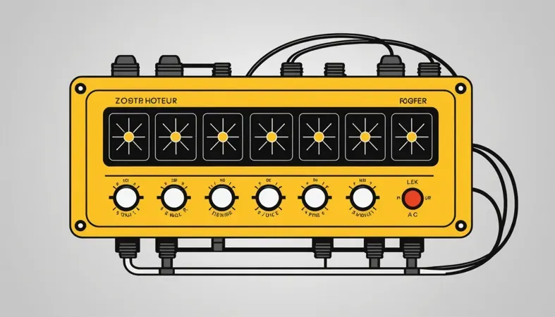
As you’re exploring options, consider a welding rectifier like the Miller Maxstar 150. It effectively converts AC to DC, much like a DIY bridge rectifier. Some folks prefer commercial models due to reliability, built-in safety features, or ease of use without complex assembly. For those aiming to enhance welding quality, understanding how to avoid spatter in welding is crucial.
Another route is using a rectifier module, such as the KBPC2504, which can streamline your setup. These modules save time and reduce the risk of errors in assembling components. Plus, they often come with specifications that ensure better performance in demanding conditions.
Ensure proper connections for optimal performance.
Frequently Asked Questions (FAQs)
Now let us look at some unique questions I typically get asked regarding bridge rectifiers.
What is a Welding Rectifier?
A welding rectifier is an electrical component that converts alternating current (AC) into direct current (DC) for welding applications. This conversion is crucial because DC provides a more stable and consistent arc, improving weld quality and penetration. When selecting welding materials, it’s important to consider what the numbers on a welding rod mean for better performance.
What Does a Rectifier Do in a Welder?
A rectifier in a welder transforms AC into DC power, allowing for efficient welding processes. DC minimizes spatter, enhances control over the arc, and is better suited for thinner materials, making it a preferred choice for most welding tasks.
Does a Bridge Rectifier Need a Capacitor?
Yes, a bridge rectifier often uses a capacitor to smooth out the output voltage. This capacitor helps reduce voltage ripple, leading to a more stable DC output, especially in applications requiring consistent welding arcs.
How Much Of the AC Cycle Does a Bridge Rectifier Work on?
A bridge rectifier utilizes both halves of the AC cycle, meaning it works on 100% of the input waveform. By doing this, it improves efficiency and maximizes the usable power for welding processes.
What is a Rectifier Welding Machine?
A rectifier welding machine is a device that uses rectifiers to convert AC to DC for welding. These machines are known for delivering precise control and consistent performance, essential for high-quality welds in various applications, including welding machines used in fabrication and construction.
Conclusion
I hope this gave you what you needed. We covered the basics of what a bridge rectifier is, the different types available, and the necessary prerequisites. Additionally, we discussed steps to build a bridge rectifier, crucial safety tips, various components, and potential issues you might face during construction.
To sum up, building a bridge rectifier for your AC welder involves gathering the right materials and following the clear steps outlined earlier. You’ll need components like diodes and a heatsink to ensure proper functionality. Wishing you success in your welding projects as you create a reliable power source for your welding needs.
For further insights and detailed information, What is Welding provides extensive resources on welding techniques, tips, and best practices that can enhance your skill set.
Additional Reading
- ISO. (2017). ISO 3834: Quality Requirements for Fusion Welding of Metallic Materials. Geneva, Switzerland: ISO.
- American Welding Society. (2018). AWS D14.3: Specification for Welding Earthmoving and Construction Equipment. Miami, FL: AWS.
- Welding Institute (TWI): https://www.twi-global.com
Joe Carter is a retired welding professional with over 40 years of hands-on experience in the industry, spanning ship repair, structural welding, and even underwater projects. Joe is a master of MIG, TIG, and Stick welding. Passionate about mentoring the next generation of welders, Joe now shares his decades of expertise and practical insights to help others build rewarding careers in welding.
AC Welder, American Welding Society, Bridge Rectifier, DIY Electronics, Electrical Engineering, Voltage Drop, Welding, Welding Components, Welding Processes, Welding Techniques, Wire Gauge
